Quantcast
Channel: Motor drivers forum - Recent Threads
Viewing all 13248 articles
Browse latest View live

DRV8848 not spinning 12V DC brushed motor, 7W

$
0
0

Hello,


i am experiencing a bit of a problem using a drv8848 motor driver in my circuit.

The drv8848 is used in parallel mode for higher output capability.

Furthermore, it is wired up as indicated in the datasheet, so the 12V dc motor is attached to Pin 5 (BOUT2) and Pin 7 (BOUT1).

For C_VM a 10µF and parallel a 0.1µF capacitance are used.

for operation (3.3V is HIGH, VM is 12V sourced by a 12V battery):

BIN1 is set to LOW
BIN2 is set to HIGH
nSLEEP is set to HIGH

Result:
The motor does not start spinning. Sometimes a short damped sound can be heard from the motor as if it starts moving but then does not.
if i use a relatively small dc motor (such a motor that is used in toy race cars etc.) it works as expected. (one output rises to about 11V, the other stays at approx. 0V).

I also tried to exchange the C_VM capacitance from 10µF to 100µF or 1000µF but nothing changes.

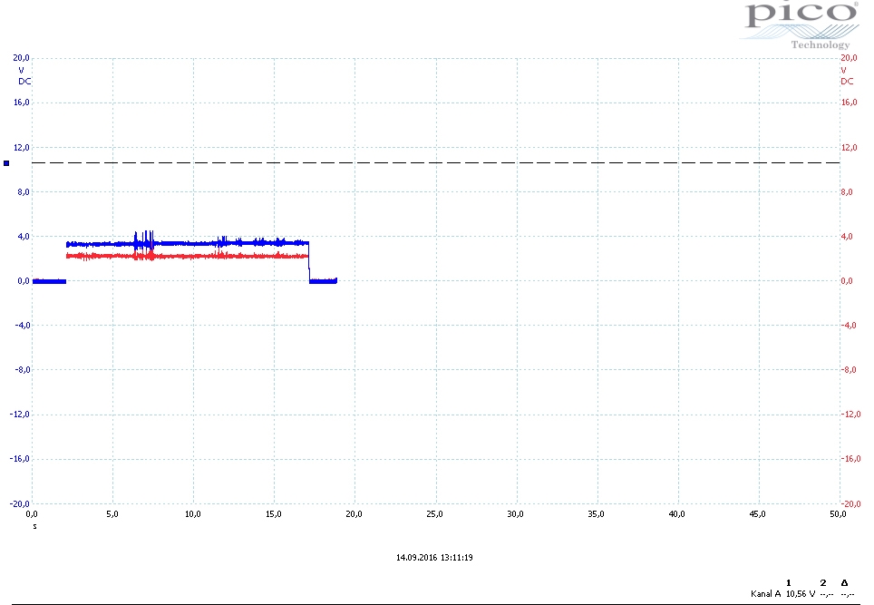
Please find attached a measurement of AOUT1|| BOUT1 and  AOUT2||BOUT2 while driving the dc motor.

Do you have any hint where there might be a problem?
Is the DRV8848 driver generally suitable for spinning this dc motor (ELVI DC Brushed Motor diameter 59mm, 7W, 12V, with Hall-Sensor)?

Thank you very much!

Best Regards
Mathias


DRV8838 protection against inductive kick, etc.?

$
0
0

Does the DRV8838 incorporate protection against inductive kick and back EMF when stopping the motor beyond the body diodes of the FETs?  Or do we need to rely on bulk capacitance and external clamping devices if we need greater protection?  We have a lot of bulk capacitance (1000 uF) and a small motor, so we may be okay, but we want to be prepared.

Thanks,

Scott

DRV8825 stepping indexer settings halving the total travel distance

$
0
0

I have a custom stepper controller board based on grbl and the DRV8825. I use NEMA 17 motors with 1.7A maximum current per phase and the machine operates at 12V (essentially the voltage at VMA/B of DRV8825 is 12V). Attached here is an image of how the microswitches are connected on my board. I used this site to calculate the steps/mm value that I need to specify in grbl. If I set M2 at 5V and leave M1 and M0 open, I should see 1/16 steps/mm resolution and based on my pulley tooth count (20) and belt pitch (2mm) the calculated value for grbl is 80. However, this does not seem to be working. With a value of 80 I seem to be halving the total travel distance in any axis. What am I missing? Is the way the microswitches are connected wrong?

DRV8305-Q1 Questions

$
0
0

Hello, please let me ask some questions about DRV8305-Q1.

  • How should pins of current shunt amplifier be treated if the amplifier is not used? SPx, SNx and SOx pins (x = either of 1, 2 or 3)
  • Only the maximum of 60 pF is recommended on the output of the current shunt amplifier, but what if an external resistor is inserted between them to form a RC LPF? The resistance value is not decided yet.
  • Can AVDD output be used to drive an external load of about 2 to 3 mA?
  • Does Figure 18 on page 45 of the data sheet surely cover all the things users must take care of? Is something else missing?
    • For example, in the figure, WAKE pin is left open, but does it in fact have to be tied to somewhere?

Best regards,
Shinichi Yokota

RE: DRV8844PWPR and Working with the Beaglebone Black/Seth

$
0
0

Hello,

My name is Seth. This may sound silly but here goes it. I am making a web based controlled or WiFi keyboard controlled mower for goofing around. I wanted to learn more about robotics and motor control. Luckily, TI.com has a Motor Driver forum. Okay, I was going to use JavaScript with my target board, the Beaglebone Black.

I found that smaller motors were not powerful enough to push my skeleton chassis and engine with blade. So, I went through my resources and found that I had purchased a H-Bridge IC awhile back. It is the L293D and it is very "weak." I do not plan on using this H-Bridge IC for production. I do want to apply 12v or higher motors to my board with a H-Bridge IC. I am going with the DRV8844. It can handle the load.

Now, will I be able to use a breadboard before producing my final product with this H-Bridge?

I wanted to ask just in case the outer pins were too small or positioned incorrectly for normal breadboards.

If anyone out there is using the DRV8844 for messing around with motors and target boards outside of the EVM, please make this discussion home. I would love to know more about you, your project(s), and how I could benefit from what you already know, i.e. as I am still new to the whole motor control phase in my life.

Seth

P.S. I use the Debian version of Linux on my BBB.

Buy Automotive 48V 1kW Motor Drive Reference Design

$
0
0

Can I buy TIDA-00281 Automotive 48V 1kW Motor Drive Reference Design System without launchpad for research and testing?

DRV8305 unused current sense amplifier pins

$
0
0

Hello Madam/Sir,

I am using drv8305 for our current design, but we used only 1 current sense amplifier. For pins of the other unused current sense amplifier, do I have to connect all the inputs and outputs to GND, or I could leave them floating? Because floating pins could probably create ESD issues?

Active Front End made of HVMotorCtrl+PFC V2.1.

$
0
0

Hello everyone.

I have a question conserning HVMotorCtrl+PFC V2.1.

Is it possible,having two of this kits, connect them together according Active Front End (AFE) + Inverter scheme?


Thanks for any help in adance


DRV8824 MICROSTEPPING Problems

$
0
0

Hi,

I'm using DRV8824 to drive a hybrid bipolar step motror(12V,0.6A,1.8°) in a microstepping mode(up to 32microstep/step), because i would like to reach a step of 0.06 degrees(around 1.8degrees/32).

My circuit, reproduces exactly the one shown on page 19 of the datasheet, except for the value of VREF, which is 1.5V to obtain a current of 0.75A of full scale.
The control pins are connected as follows:
Enable (connected to GND)
Sleep (+ 5V)
Home and FAULT (Pull Up +5 through 10 Kohm resistor)
Steps Imput is  5V amplitude  1Hz Frequency

As long as I select the full mode or half mode everything works fine, but starting from fourth on engine no longer has a fluid movement, but does little jumps, and when I select 32microstep / step motor is not moving and emits a sort of hiss.

can you help me??

Sellecting driver for 28BYJ-48 stepper motor

$
0
0

Greatings! I want to build a small pcb for 28BYJ-48 stepper motor. As fas I know it`s draining about 200-250mA on 5V. Can you help me with the driver sellection. My first choise is DRV8711, but I`m concern about the driver is running on min 8V, but the stepper motor is on 5V. Is there a problem? Do I have to sellect another driver. I`m not sure how much of there 8V will be passed to the driver. 

Thanks!

UC2625 TACH-OUT

$
0
0

Hi, folks,

> Any change in the H1, H2, or H3 inputs loads data from these inputs into the position sensor latches

Is this means that there will be 6 times of TACH-OUT signals on 1 rotation?

DRV8825 holding torque

$
0
0

I got my setup with the DRV8825 working nicely. I even did a few test prints for my laser cutter using grbl and they came very precise. I have one question though. Earlier I was using the Allegro A4988 drivers and every time I'd switch on the supply I would get a holding torque which would prevent me from moving the axes manually. However with the DRV8825 drivers I can still move the machine manually when the supply is switched on. Is this normal? The driver setup is mostly the stock reference from the datasheet. I've attached the schematic of how they are wired in my setup.

I'm using NEMA 17 motors that support upto 1.7A per phase and with the current limit set at 1.5A (Vref is 0.75V with 0.1R sense resistors). 

DRV8834EVM serial command list

$
0
0

Dear Support team,


We want to control DRV8834 with our external command instead of FTDI USB chip.

Is it possible to disclose the list of commands and the serial I/F specification of RX/TX for MSP430?


Best regards,

Hiro Takahashi

drv8825 - Ipeak accuracy

$
0
0

Hello Motor driver Experts,

I have a general question regarding understanding the current accuracy on the DRV8825. Data sheet shows a table of current accuracy versus

Let's look at an example:

IPeak =  Vref / (5*Resnse) = 1.5V / (8 5* 0.5 Ohm )= 600mA

Running 71% current setting resulting in the current will be 600mA * 71% +/- 5% = 426mA +/-21.3mA ( 5% of 426mA ) . Or is it 600mA+/- 30mA ( 5% of 600mA )

Would this current value contain all error sources incl. Vref tolerances and gain variations but excluding the tolerances  on Rsense?  Or how is the information in the table to be understood?

I need to be able to predict the total tolerance on the trip current..

DRV8842

$
0
0

HELLO,

HOW TO USE IN1 AND IN2 PINS IN DRV8842 

IF I HAVE TO GIVE A GENERATED PWM  FROM CONTROLLER AND CONTROL THE LOAD CURRENT USING I0-I4 SETTING 

(CAN I GIVE DIRECTLY SAME PWM TO IN1 AND IN2)

THANKYOU.


PWM signals control

$
0
0

Hi Everyone 

I am using HVDMC Kit R1.1, F2803X,  The code I am using is "Sensored Field Oriented Control of 3-Phase Permanent Magnet Synchronous Motors" . I would like to switch off one of the PWM signal (EPWM1A, for example) without effect to the other PWMs signals (EPWM1B is working as normal not invert of EPWM1A , for example)

Does anyone have any idea how can I do this?

Regards 


Need Help on DRV8711 micro step size

$
0
0

I'm using Infineon XMC4500 to drive DRV8711.

The motor made so much noises when I set it to 256 and 128 micro step size, 120+ rpm. It didn't make that much noises on 64 micro step size.

When I tried using DRV8711 EVM and set it to 256 and 128 micro step size, 12)+ rpm, it was much more quite and smoothly.

The registers settings are the same in both cases, so I don't know what's wrong.

Here are the registers settings:

Register 0:

ISGAIN = 40

DTIME = 850ns

Register 1:

TORQUE = 123(Decimal)

SMPLTH = 001

Register 2:

TOFF = 20 us

Register 3:

TBLANK = 3 us

ABT = 0

Register 4:

TDECAY = 10 us

DECMOD = 101

Register 5:

SDTHR = 60 (Decimal)

SDCNT = 00

VDIV = 10

Register 6:

OCPTH = 00

OCPDEG = 00

TDRIVEN = 11

TDRIVEP = 11

IDRIVEN = 00

IDRIVEP = 00

Register 7:

all zeroes


everything else is in default setting.


Here is my acceleration code, I have a hardware timer expires every 1ms:

steps_per_second = RPM * ustep_size * (360 degree / 1.8 (degree per step) );

accel = (steps_per_second - 0 )/acceleration_time; //I set the acceleration time to 500ms

voidTime_Interval_Event(void)

{

TIMER_ClearEvent(&AccelTimer);

PWM_SetFreq(&MotorStep,current_steps_per_second);

current_steps_per_second = current_steps_per_second + accel ;

if(current_steps_per_second > steps_per_second ){

PWM_SetFreq(&MotorStep,steps_per_second);

TIMER_Stop(&AccelTimer);

TIMER_ClearEvent(&AccelTimer);

}

}

This is how I calculate the acceleration, I skipped other settings such as the timer, because it's working fine

So why does the motor make so much noise on my board with the same settings of drv8711 evm?

(Also drv8711 evm can't go faster than 30 RPM when it's set to 256 micro step size due to the chip)

Could you please take a look at my spi settings and acceleration calculation? Thanks!

Esme


DRV8305 paralleling Mosfets

$
0
0

Hello TI Team. 

I'm currently designing a motor controller around the DRV8305.

At the moment i am about to consider using 2 mosfets in parallel all the places in the inverter. So 12 Mosfets in all. The design recommendation is to do as little as possible between DRV8305 and the mosfets (no gate resistance etc.) while using the DRV8305 to limit current.

To my question, if i am paralleling the mosfets that the gatedriver is supplying, will the DRV8305 be able to quickly switch the FETs without ringing? Even while not using any gate resistance and so on?

I hope my question is clear enough. 

In short will the DRV8305 be able to Switch paralleled FETs? Even with out using individual gate resistances?

Kind Regards Rasmus

DRV8811 data sheet Question, Urgent

$
0
0

We got some customer technical question.


In DS Pg.7, we can check the timing diagram and definition of each time spec.


  1. In 6, wake up time spec, what does it mean of this?

In sleep mode operation, sleep mode will disable when sleep pin is high. But it looks like we should input STEP signal in maximum 1ms. Should we do this?

I cannot understand its intention.


    2. In 9, Disable time

  1. Is it typo this description? IC will operate when Enable is low and disable when enable is high. Customer checked when enable is high and time to output is disable.

    But in this timing diagram, I think it is different what I and customer understood and tested. What is intention of this spec?

  2. What does Inactive high means? Active low? Or just low. It make us confused.


Regards,

Motor Drive IC Selection

$
0
0

Hi Team,

The customer needs to select  the motor drive IC for BLDC. He need two types motor drive ICs. One has the Integrated MOS and another does not have the Integrated MOS.  And the motor voltage is 48V.  The two type  motor drive ICs can achieve the closed-loop control for the position, speed and current of the motor.

Please recommend the suitable ICs.  Are DRV8832 and DRV8302 OK? 

Can DRV8303 replace DRV8302? Can DRV8312 replace DRV8832?

Thanks,

Best Regards,

Viewing all 13248 articles
Browse latest View live


<script src="https://jsc.adskeeper.com/r/s/rssing.com.1596347.js" async> </script>