Attached is a curve of the 3 phase BLDC motor I am trying to drive. I would like to have a supply voltage, to the driver, of 115vAC and the ability to control the speed/power supplied to the motor. 
 What BLDC motor driver should I select?
↧
What BLDC motor drive should I use?
↧
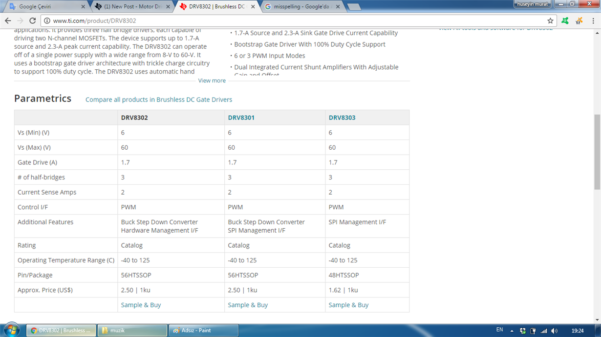
DRV8301 vs DRV8302 operating voltage
Hello,
According to datasheet DRV8301 and DRV8302 are almost the same device except the programing method (8301 is spi , 8302 hardware programable).
But their operating voltages are not same . DRV8301 works 6-60V, but 8302 works from 8-60. Why their operating voltages are different?
In the parametric searh their operating voltages seem the same (both 6-60V) but in the datasheet for 8302 operating voltage is shown as 8-60V. I think there is a mistake in the datasheet or parametric search tab.
↧
↧
Trying to break the DRV8850
I am trying to break the DRV8850. I have tried to do a reverse while the motor is still free spinning but this has a tendency to pop my DC to DC converter that is supplying it. What I mean is it causes the Boost converter output FET to short open.
Is there a better way to break the motor. I am using this motor on a slide for precise position and speed control. Is there a better part.
Stall current is 4A, Nominal Current 660mA .
Supply voltage Min 3.0V - 4.75.
~Chris
↧
DRV 8313 evm issue in uploading bootloader
Sir ,
I tried the motor to run in standalone mode, but getting the error(below is the screen shot). PLS help me out.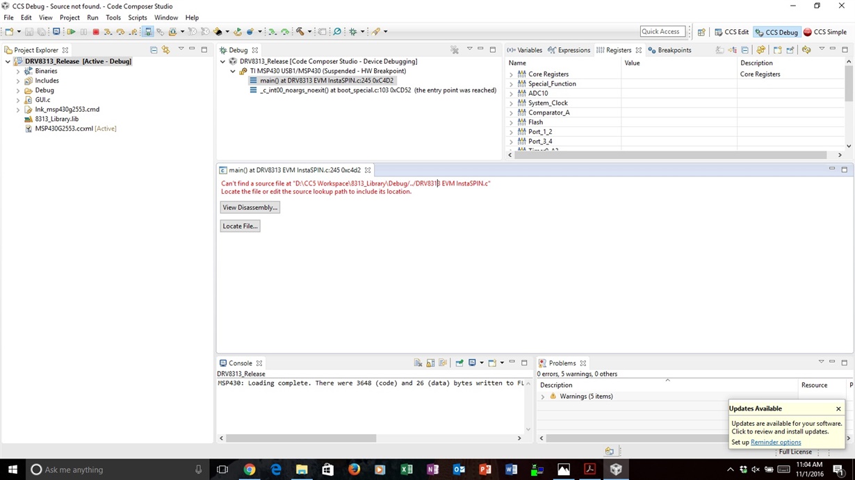
↧
Access missing ADCs on DRV8301x-HC-C2- kit
I have to implement torque control using DRV 8301 HC-2 kit. However, from the schematics (1222.DRV830x-HC-C2-KIT_HWGuide), it seems that ADC A0, A4, A6 and B6 channels are not accessible. Are there external GPIO extender boards that can let me access these ADCs?
↧
↧
Dual DRV8835 Control Interface
Hello Team,
I've got a motor driver system level question for you. I'm looking at using 2 DRV8835s to drive 4 Brushed DC motors using the Phase/Enable control mode. That's the easy part.
I want to use an I2C interface from my uC to create the 8 PWMs required to control the 2 DRV8835s. I would very much not like to use another uC to accomplish this. Do you have any suggestions on how to go about converting my I2C into 8 PWMs?
I've looked at your I2C I/O Expanders and they don't support PWM functionality, only GPIOs, which correct me if I'm wrong but won't be able to control the DRV8835s. (around 20kHz PWM needed). I've also looked into your LED Drivers, but there isn't quite a good fit there either. Jose's blog gave me hope that you may have see this need before and would have an idea of how to tackle it.
Here is a simple diagram of what I would need to accomplish:
(Please visit the site to view this file)
Thanks for your help,
Hayden
↧
drv8302
Can i use DRV8302 to drive 3 phase H-bridge in sign-magnitude drive mode (toggle both high side and low side MOSFETs in PWM signal)??
↧
DRV8308 - VREG not coming up
Part Number: DRV8308
Application: Sensored BLDC driver for consumer electronic product
Question type: Development and troubleshooting
Description of the problem: Hi, I was using DRV8307 to run my BLDC, it worked fine. When I upgraded to DRV8308 the VREG in the chip is not coming up. I have checked for shorts in bypass capacitors, and pullup pulldown resistors, nothing is short. Programming is clear from the microcontroller side (SPI registers are written properly). Voltage at VINT is about 1.3V. VM is 15V. Enable pins state is not changing the VREG state (it is always 0V )
Thanks.
↧
DRV8711- Relation between sine current wave and PWM frequency and Vm
Dear friends
I put a 8 pin deep micro switch to change tha value of torque in DRV8711. By changing the Torque value, fortunately I succeed to obtain the reasonable the sine cuurent graph. But when I change the Vm or PWM frequency this wave is destroyed. In result I must change the value of torque.
1- Is there any relation between the PWM frequency and Torque?
2- Is there any relation between the Vm and Torque?
3- I do the same experints on DRV8825 and this deriver has also the same problem. As you know we need to change the speed of stepper motor in our devices during time.
Pleses help us kindly to deal with this problems.
Many Many Thanks.
Hadi
↧
↧
BOOST-DRV8711 dimensions and mounting provisions
Can you please provide the dimensions and any available mounting provisions for the BOOST-DRV8711?
↧
Stepper load detection via Back-EMF with the DRV8711
Matt Hein did a couple of blog posts about using BEMF as a load sensing tool, but they were never completed.
In my own testing, I've seen some traces that make me think it's possible. Attached is a .gif of a pair of traces. The sine is the current in phase 1A, the green is the BEMF pin, measured across the required capacitor, right on the BOOST-DRV8711 board (yes, I know it looks ugly).
24V Vm
2.1A 1.8d motor
4,8mH/phase
1.8R/phase
NEMA23 frame.
Loaded:

Unloaded:

Has anyone successfully used BEMF to track stepper load? I know that BEMF tracks mainly with RPM, and load is a minor component, but it seems like something that Trinamic and others are using to some effect.
My thought is that the large differences that center around the bottom half of the drive sine could be used as a per-cycle indicator of load. Yes, it's specific to my motor and my mechanical arrangement, but in general, I think this may have applications beyond my simple constant-speed drive.
↧
TIDA-00472 Sensor less motor driver
Hallo i am Torge,
i would like to build a application for a brush less motor with around 100 watt.
The TIDA-00472 is already very close to the application with i like to get running.
There are just some small devices to add is it possible to get the Eagle files of this application.
Thanks Torge
↧
drv8432 problems
Hi team,
The chip DRV8432 has internal current limit says 15A.
And the chip also can configure the current limit threshold by resistor, but the current only can be 12A as the datasheet says.
Can my customer use a smaller resistor to get the 15A current limit ( for example 16.5kohm)?
Thank you.
BR
Frank
↧
↧
About the DRV10983
Hi
I have a question about the DRV10983.
1,
120° and 180° is switched automatically by the conditions?
(Customer want to use always 180°)
Other competitor device is automatically changes 120 and 180.
www.semicon.sanken-ele.co.jp/.../si-6635m_ds_en.pdf
Best regards,
masa0301
↧
DRV10983 about the using I2C
Hi
I have a question of the DRV10983
1,
Although the type of speed controller is built in.
How many second the PID updata time?
2,
How many seconds need the update speed controll cycle of the using I2C?
Customer expect within the 1ms.
Best regards,
↧
FAN Controller IC recommendation
Team,
I have 2 heatsinks with integrated blowers on the board and want to control the fans with the simplest fan controller.
It should:
1) run completely on its own (also using fan tacho)
2) have the possibility to use i2c / smbus
3 ) if possible dual in order to control 2 fans individually
Which device do you recommend?
Please let me know
Thanks
↧
Controlling a bldc motor of 24 volts. Which driver is the ideal?
Hello, I have a bldc motor and I want to build the driver for the control because I was investigating and some driver are expensive.
My motor is the next:
Here is the datasheet:
http://www.mopselectric.com/ebay/nidecbrushless.pdf
I thought that I can use the driver DRV10983 with Arduino to control the motor.
http://www.ti.com/product/DRV10983/description
Which driver do you recommend? I need your help. Thanks
↧
↧
How to select an evaluation board for BLDC Motor with 48V and 20A maximum current.
Hii I'm using a hub motor with 48V and 20A maximum current. I want an evaluation board and also what driver will work for that current and voltage. TIA
↧
DRV8301 questions soldering temperature
Hi, I am building a custom board using DRV8301. I have build one last year and made it work. However, it suddenly broke. The 3.3 buck converter module is working but the FETs are not switching. My schematic is quite similar to the one in the datasheet but I am using 48-54V LiFePo4 as source and I have in parallel with the device 2 24V horn(2A max) in series. My 6 Fets have Qg (labeled as Total charge in tha datasheet) of 207nC max each. I am running at 8000Khz with 1Ohm gate series resistance. I am not sure if it is Qg or Qgs(48nC) that I will use in the Gate drive average load.
So I modified the board and quite having difficulty hand soldering the chip. I already wasted 2 because it was not aligned and it is hard to desolder. I was able to solder 1 successfully but not sure if it was overheated because I was using a hot air blowing 290-350 degrees Celcius. I have not tested it because I am waiting for my MCUs to arrive. But I want to know if the temperature was very high so that I can reorder the chips.
Where can I see the soldering profile for this chip?
↧
TIDA-00771 BLDC drive firmware questions
Hi, I'm reading the firmware of TIDA00771.
I found that the SPI is implemented with four IO ports, not the SPI module in MSP430G2553, why?
Moreover, the readregister function is as below:
uint16_t ReadRegister(uint8_t address)
{
uint16_t reading;
reading = ReadOnce(address); //once
delay_1us(1);
reading = ReadOnce(address); //twice
return reading;
}
why do we need to read the register twice?
And in main.c, there is only "ReadRegister(0x01)", it makes no sense because the "reading" result is not given to any variable. I think it should be
"faulttype= ReadRegister(0x01)" for example.
Thanks.
↧